Electronic water treatment
more info on the website - www.elektronicka-uprava-vody.cz
- A principle of function of electronic water treatment
- Advantages of AntiCa++ devices
- Principles of correct use of AntiCa++ devices
- Properties of treated water
- Types of equipments
- Specifications of devices AntiCa++
- Installation of AntiCa++ devices
A principle of function of electronic water treatment
A release of ions of hydrogen carbonate from electrostatic bonds with molecules of water takes place due to the activity of the precisely defined magnetic field, which is created by a coil coiled on the water piping with subsequent formation of the aragonit crystals which are not able to form hard deposits. These crystals are washed out from open systems, and it is possible to catch them in closed systems simply in mudtraps and discharge.
Advantages of AntiCa++ devices
- simple installation without putting the piping out of operation
- service without operation and maintenance
- without any hygienic hazards - devices are not in contact with water
- long service life ( min. 20 years )
- low purchasing cost in comparison with the other processes of water treatment

Properties of treated water
Closed systems:
1. For hot water andsteam boilers with large outputs, it is convenient to use AntiCa++devices for an additional water treatment to its chemical treatment using ion-exchange cleaners (cationexchangers). In this way, a slow scaling and subsequent failures of boilers will be prevented which often occurs in practice afterseveral years service. Total replacement of chemical treatment requires often and perfect sludge blow-off of boilers and their regular inspection. Energy losses during sludge blow-off can be reduced by filtration of blow-off water and by its filling back.
2. For boilers with small outputs and for various steam generators the devices entirely replace chemical water treatment. They can be installed either near the circulating pump, or on the branch pipe, through the volume of water flows during 24 hours, which equals to the entire volume of heating system. These equipments also require regular sludge blow-off.
3. The manner of use is also similar for cooling and air conditioning systems.
Open systems:
4. In exchanger plants, the device can be installed either on the supply line of cold water to the exchanger, or on the circulating piping. In the latter case water is treated only partially, therefore it is necessary to consider thorougly this type of installation. for modern, highly efficient small exchangers, the devices must be installed on their supply line exclusively.
5. In the all other cases, it is advantageous to install the devices on supply waterline of the house, plant etc.
Properties of treated water
- it does not create solid deposits of boiler water
- it dissolves its old deposits
- it forms the anticorrosive layer of Fe3O4 on metallic surfaces
- it saves washing means
- it affects favourably growth of plants
- under certain conditions, it increases the strength of concrete
- the content of mineral substances remains unchanged in it
These favourable properties of water last for a certain period of time (2 - 5 days), which depends on several factors (the content of individual minerals, CO2 dissolved in water, etc.). After this period has expired, there versible process takes place. It is necessary to calculate with it for individual applications.
Types of equipments
During selection of the convenient type of the device, it is necessary to take into consideration the following data:
- Range and time course of the flow water in the place of installation
- Diameter of piping
- Manner of control of the device in the case of flow water variable rate
|
|
Devices EUV 10D - 65D are designed for exchanger plants in blocks of flats. They allow to switch the devices in two flow rate zones ( I. low, II. high )either in 24 cycle, or in 168 hr. cycle using the time relay. The switching contact, which is bound on the protected technological equipment. |
|
|
Devices EUV 32T - 65T are designed for exchanger plants in blocks of flats. They allow to switch the devices in two flow rate zones ( I. low, II. high )either in 24 cycle, or in 168 hr. cycle using the time relay. The switching contact, which is bound on the protected technological equipment. |
|
|
Devices EUV xx MI are designed for applications, where the flow rate is constant, and given by circulating pump. For example cooling the compressors ammonia, air-conditioning, heating, etc. The optimum level is set manually according to the used pump. |
|
|
Devices EUV xx TI include properties of EUV xx T and EUV xx MI, i.e. they allow switching two manually preset zones of flow rate using either time relay or auxiliary relay, e.g. in laundries. |
|
|
Devices EUV xx AI are designed for applications, where the flow rate fluctuates irregularly in a wide range. The optimum level for these types is set automatically according to the signal from the flow meter. The type of used flow meter must be stated in the order. |
Note:
Devices EUV 10 - 65D, EUV 32 - 65 T are equipped with the output for both magnetic (Fe ) and non-magnetic piping ( Cu, stainless steel, plastic ). For EUV ...xI devices it is possible to set the optimum efficiency of water treatment in dependence on the flow rate forall types of piping.
Specifications of devices AntiCa++
|
Specifications of devices Anti Ca++
|
|||||
| Type of device |
Optimum range of flow rate (m3/hod) |
Internal piping diameter
(mm - inch) |
Dimensiony
WxHxD (mm) |
Power input (W) |
Characteristic and use |
| EUV 10 D | 0,10-0,45 | 10-3/8' | 160x96x67 | 2 |
Non-controlled devices for households and small plants:
|
| EUV 15 D | 0,30-1,00 | 15-1/2' | |||
| EUV 20 D | 0,60-1,80 | 20-3/4' | |||
| EUV 25 D | 0,90-2,70 | 25-1' | |||
| EUV 32 D | 1,40-4,40 | 32-5/4' | 3 | ||
| EUV 40 D | 2,30-6,80 | 40-6/4' | |||
| EUV 50 D | 3,50-10,5 | 50-2' | |||
| EUV 65 D | 6,00-18,8 | 65-1 1/2' | 315x130x83 | 4 | |
| EUV 32 T |
I. 0,40-1,40 II. 1,40-4,40 |
32-5/4' |
Timer controlled devices in two zones of flow rates (e.g. "day-night") designed for:
|
||
| EUV 40 T |
I. 0,80-2,30 II 2,30-6,80 |
40-6/4' | |||
| EUV 50 T |
I. 1,20-3,50 II. 3,50-10,5 |
50-2' | |||
| EUV 65 T |
I. 2,00-6,00 II. 6,00-18,0 |
65-2 1/2' | |||
| EUV 50 xl | 0,2-25 | 50-2' | 275x220x140 | 6 |
x = M Devices with manual setting from one to ten flow rate zones: heating and conditioning systems, compressor systems, etc.
x = T Devices with timer control in two preset flow rate zones.
x = A Devices with automatic regulation from flow meter.
|
| EUV 65 xl | 0,3-42 | 65-2 1/2' | |||
| EUV 80 xl | 0,5-54 | 80-3' | |||
| EUV 100 xl | 0,8-65 | 100-4' | |||
| EUV 125 xl | 1,4-130 | 125-5' | |||
| EUV 150 xl | 2,0-190 | 150-6' | |||
| EUV 200 xl | 3,2-340 | 200-8' | |||
| EUV 250 xl | 6,0-540 | 250-10' | |||
| EUV 300 xl | 8,0-760 | 300-12' | |||
| EUV 400 xl | 13,0-1360 | 400-16' | 275x370x140 | 10 | |
| EUV 500 xl | 24,0-2160 | 500-20' | |||
Installation of AntiCa++ devices
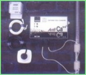
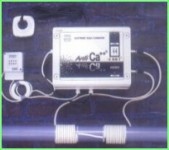
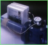
The installation is very simple, it does not require any plumbing jobs. It is based on coiling a coil from the power cable on the piping and on fixing the device on the wall or another vertical surfaces. When the timer controlled devices or devices with regulation of the flow rate are used, the device will be connected with the time relay or with respective flow meter. The device must be installed close to electric power outlet 230VAC.
Interested? Do you have questions? Would you like to receive a price offer? Do you need a custom made solution? Do not hesitate to contact us on +420 608 776 299, at info@rsaquatech.cz or through our inquiry/ contact form!
You can also buy the electronic water treatment device at our e-shop.


